What is a GNC system? Which is its applicability spectrum within space missions?

GNC means “Guidance”, “Navigation” and “Control”. The strict sequential order would be: 1) the Navigation (the part of the system than provides an estimation of the position, velocity and attitude of our system), 2) the Guidance (computes the reference state, position, velocity and attitude to go from where the system is to where the system wants to be) and 3) the Control (computes the actions –usually forces and torques- that are necessary to follow the reference state provided by the Guidance). This « definition » is applicable to all types of systems: a car, a robotic arm, a satellite, a deep-space probe or even a human being.
But let’s make it simple. The GNC is, in few words, the satellite driver. Thanks to it a space probe can go left, can go right, can go softly on the Moon or Mars, can impact an asteroid.
Behind this generic definition, the differences between the on-board GNC subsystem for different types of space missions is enormous because of the differences within the scenario dynamics laws, the available sensors (“the GNC eyes”), the available actuators (“the GNC arms and feet”) and the ultimate purpose/objective/requirements of the spacecraft (the reasons why it is flying). While the core algorithmic technologies used for the three on-board GNC functions are many times common, the application to the different space scenarios is most of the times very different. On the other side all GNC systems are organized in “modes” (which are different instantiations of the GNC as per specific needs/phases of the mission) managed by a dedicated GNC Mode Manager functionality and, usually, a dedicated Failure Detection, Isolation and Recovery (FDIR) function is also present within the on-board GNC subsystems.
The “Navigation” function is usually based on a recursive (to allow propagation over the time in case of need and to get “memory” of effects that endure over the time) filters aiming to fuse the different available metrology measurements. The attitude estimation and the position/velocity (PV) estimation are typically decoupled but, in certain scenarios, the attitude and the PV estimation are coupled and the filter state vector shall include many states (including also estimation of other relevant parameters such as unknown measurements biases that shall be estimated to improve the ultimate navigation accuracy). The most common used filters are Kalman filters (in its multiple variants).
The “Control” function is usually based either on classical technics (such as PD/PID) or, most ofent nowadays for demanding scenarios, on robust techniques (such as µ-techniques or H∞). Robust techniques allows to guarantee the control performances in presence of uncertainties (due of space perturbations or system uncertainties, such as inaccurate knowledge of the center of mass, solar arrays flexible modes or fuel sloshing).
The “Guidance” function is the one that is much more scenario dependent than the other two because is much more related to solve dynamics laws of the specific scenario.
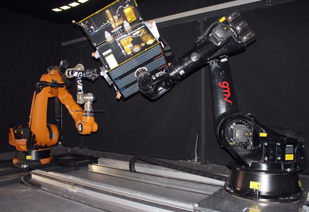
In terms of scenarios and GNC application to the scenarios, a GNC can drive (non-exhaustive list): satellites in circular Low Earth Orbits (e.g. Earth Observation satellites), satellites in circular MEO/GEO orbits (e.g. telecom satellites), satellites in orbital equilibrium points, such the Lagrangian points (e.g. telescopes), satellites in highly elliptic orbits (e.g. PROBA3 where the apogee part of the orbit provides a significant unperturbed condition allowing precise science objectives such as the Sun corona observation), inter-planetary satellites (e.g. travelling to the Moon, Mars or asteroids), satellites in orbit around non-Earth central body (e.g. orbiting the Moon or Mars) or a very weak gravity central body (e.g. orbiting a Mars moon or around an asteroid/comet), planetary re-entry probes (with atmosphere such the Earth or Mars), planetary landing probes (without atmosphere such the Moon), launchers, planetary exploration rovers, asteroid samples collectors, … The previous list refers to single-spacecraft missions. When talking about multi-spacecraft missions, a GNC can drive the cleaning of the space surrounding the Earth (orbital debris removal) or the repairing of broken platforms (servicing missions where a servicing spacecraft shall approach and interact with another spacecraft, controlled or uncontrolled, for repairing or refuelling), formation flying missions (where two or more spacecraft shall fly in formation acting as in a single rigid virtual structure, for instance PROBA3 mission during the apogee phase of the high elliptic orbit, or telescopes that need a longer focal length that what is achievable with a single physical structure such as the new expected generation of telescopes for exo-planets detection), swarms of collaborative satellites or swarms of planetary exploration/infrastructure building rovers. GMV, through its Business Unit dedicated to Flight Segment and Robotics, has participated in activities related to GNC for all these scenarios throughout its extensive experience (mainly with the European Space Agency) in the last 30 years.
For all mentioned missions/spacecraft, the attitude estimation is usually based in the combination of three sensors: Sun Sensors (to detect the Sun and guarantee the possibility to orientate the solar arrays towards the Sun after separation from the launcher and/or in case of problems during the mission), Star Trackers (to get accurate orientation information with respect to the stars) and gyroscopes (to be able to propagate the attitude estimation when the attitude rate is higher than the limit of the Star Trackers or to detect/correct a situation where a non-desired high attitude rate is present, such a thruster failure, a collision with a debris, or a failure in the launcher separation). The position and velocity estimation is usually based on the use of on-board GNSS receivers (in orbits around the Earth) and ground based ranging measurements (for inter-planetary or very high Earth orbits). For multi-spacecraft missions or planetary surface missions, the relative navigation is usually based on the use of cameras (visual, infrared) and laser (e.g. Lidar) sensors, combined with 2D/3D images processing techniques to get knowledge/awareness of the position and orientation of the spacecraft with respect to the surrounding (a second spacecraft in the case of debris removal/servicing missions or the surface topography in the case of a surface rover). The actuation means usually relies on thrusters and reactions wheels in the case of orbital spacecraft (combined with robotic devices/manipulators for servicing missions) and wheels/jumpers in the case of surface rovers.
All this, with the idea of flying far and safe!
Author: Pablo Colmenarejo Matellano


Comments